Steel Beam Shear Check Explained: Eurocode 3 Design (EN 1993-1-1 §8.2.6)
Shear forces are internal forces that resist the tendency for one part of a structural member to slide relative to an adjacent part. Ensuring a steel member's cross-section has adequate shear resistance is a critical design step, especially for beams and columns under transverse loads. This guide explains the shear verification process according to Eurocode 3 (EN 1993-1-1), focusing on plastic shear resistance and the crucial concept of the shear area.
What is a shear force?
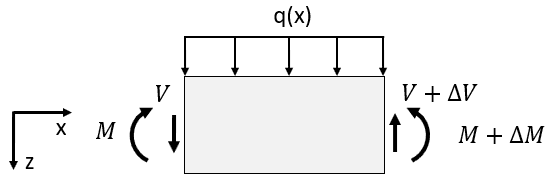
Shear force (\(V\)) arises primarily from external loads applied perpendicular to a member's longitudinal axis and the corresponding support reactions. It represents the sum of vertical forces acting on one side of an imaginary cut through the member. High shear forces typically occur near supports or points of large concentrated loads.
Eurocode design shear resistance (EN 1993-1-1 §8.2.6)
The design check
According to §8.2.6(1), the design value of the shear force (\(V_{Ed}\)) at any cross-section must satisfy:
Where \(V_{c,Rd}\) is the design shear resistance of the cross-section. The code allows for this resistance to be determined based on either plastic or elastic design principles.
Plastic vs. elastic design approach
For most common hot-rolled and welded sections that are not susceptible to shear buckling (see check below), the plastic shear resistance (\(V_{pl,Rd}\)) can be used for \(V_{c,Rd}\). This method assumes the shear stress yielding (\(f_y / \sqrt{3}\)) is reached across the effective shear-resisting area of the cross-section. Elastic verification is generally more complex and conservative (§8.2.6(4, 5)) and often only needed in specific cases or if plastic resistance cannot be utilized.
Quick Eurocode Shear Strength Check
Need results fast? Input your parameters into our Eurocode-based interactive calculator.
Go to Calculator →Calculating plastic shear resistance (\(V_{pl,Rd}\))
The formula
The design plastic shear resistance, assuming no torsion is present, is given by §8.2.6(2):
- \(A_v\) is the shear area of the cross-section (explained below).
- \(f_y\) is the yield strength of the steel.
- \(\sqrt{3}\) comes from the Von Mises yield criterion relating shear yield stress to tensile yield stress.
- \(\gamma_{M0}\) is the partial safety factor (typically 1.00).
Determining the shear area (\(A_v\))
The shear area represents the portion of the cross-section effectively resisting the shear force. Its calculation depends on the section shape and the direction of the shear force (§8.2.6(3)). For common cases:
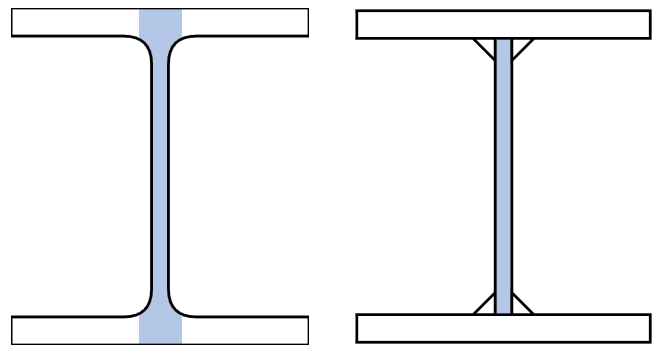
- Rolled I and H sections (load parallel to web): \( A_v = A - 2bt_f + (t_w + 2r)t_f \ge \eta h_w t_w \).
- Welded I, H, and Box sections (load parallel to web): \( A_v = \eta \sum (h_w t_w) \) (Sum of web areas multiplied by η).
- Rolled Channel sections (load parallel to web): \( A_v = A - 2bt_f + (t_w + r)t_f \).
- Rectangular Hollow Sections (RHS, load parallel to depth h): \( A_v = A h / (b + h) \).
- Circular Hollow Sections (CHS): \( A_v = 2A / \pi \).
Where \(A\) is total area, \(b\) breadth, \(t_f\) flange thickness, \(t_w\) web thickness, \(h_w\) web height, \(r\) root radius, \(\eta\) factor from EN 1993-1-5. The factor \(\eta\) is defined in EN 1993-1-5 and can often be conservatively taken as 1.0, but may be 1.2 for certain steel grades and the National Annex.
Shear buckling check (EN 1993-1-5)
Critical Limitation: The plastic shear resistance check (\(V_{pl,Rd}\)) is only valid if the web is not susceptible to shear buckling.
When is shear buckling verification required?
Shear buckling must be considered if the web's depth-to-thickness ratio (\(h_w / t_w\)) exceeds a limit related to the material (\(\epsilon = \sqrt{235/f_y}\)) and the factor \(\eta\):
Where \(h_w\) is the web depth, \(t_w\) is the web thickness. If this condition is met, the web is considered slender in shear.
What if buckling check is needed?
If the web is slender according to the check above, the design shear resistance \(V_{c,Rd}\) is not \(V_{pl,Rd}\). Instead, it must be calculated as the design shear buckling resistance (\(V_{b,Rd}\)) according to the rules in EN 1993-1-5. Web stiffeners are taken into account in this calculation. This is outside of the scope of this guide.
Elastic shear stress verification (Optional check)
If it is not possible to make a plastic design check, then the Eurocode also provides a method for checking the elastic shear stress (\(\tau_{Ed}\)) at any point in the cross-section against the elastic shear strength:
Where the elastic shear stress is calculated using the classic shear formula:
(\(S\) = first moment of area of the portion above/below the point, \(I\) = second moment of area of the whole section, \(t\) = thickness at the point). However, the code notes this is conservative and typically only necessary if the plastic resistance or buckling checks cannot be performed. For standard I/H sections, a simplified check based on average shear stress in the web is also given (§8.2.6(5)).
Practical considerations
- Fastener holes: Usually ignored in the main body of the member for shear checks, but must be considered in connection zones according to EN 1993-1-8.
- Interaction with torsion (\(T_{Ed}\)): If torsion is present, the plastic shear resistance \(V_{pl,Rd}\) must be reduced.
- Interaction with bending moment (\(M_{Ed}\)): If the shear force \(V_{Ed}\) is high (typically > 50% of \(V_{pl,Rd}\)), the bending moment resistance \(M_{Rd}\) may need to be reduced (§8.2.8).
- Stiffeners: For slender webs requiring shear buckling checks (EN 1993-1-5), transverse stiffeners significantly increase shear resistance.
Frequently Asked Questions (FAQ)
What is the shear area (\(A_v\))?
It's the part of the cross-section assumed to resist shear forces when calculating the plastic shear resistance. For I/H sections, it's primarily the area of the web(s). For hollow sections, it's related to the total area. Specific formulas are given in EN 1993-1-1 §8.2.6(3).
When must I check shear buckling according to EN 1993-1-5?
You must check shear buckling if the web slenderness \(h_w / t_w\) exceeds \(72 \epsilon / \eta\). If it does, the shear resistance is governed by EN 1993-1-5, not by \(V_{pl,Rd}\).
Can I always use the plastic shear resistance \(V_{pl,Rd}\)?
You can use it if the section is not slender in shear (i.e., the shear buckling check in §8.2.6(6) is NOT required) and if torsion effects are negligible or accounted for separately.
Do holes always reduce shear capacity?
According to §8.2.6(7), fastener holes generally do not need to be considered when checking the shear resistance of the member's cross-section itself, unless you are specifically checking the connection zone according to EN 1993-1-8.
Conclusion
Verifying the shear resistance of a steel cross-section according to Eurocode 3 involves checking the design shear force (\(V_{Ed}\)) against the design shear resistance (\(V_{c,Rd}\)). For sections not prone to shear buckling, this resistance is typically the plastic shear resistance (\(V_{pl,Rd}\)), calculated using the appropriate shear area (\(A_v\)) and material properties. However, it is crucial to first check if shear buckling verification according to EN 1993-1-5 is required based on web slenderness, as buckling often governs the design for slender webs. Remember to also consider interactions with bending and torsion where applicable.