Combined Axial Force & Bending Moment Checks (Eurocode 3 EN 1993-1-1 §8.2.9)
Structural members like columns in frames or beams supporting eccentric loads are often subjected to both axial forces (\(N\)) and bending moments (\(M\)) simultaneously. Eurocode 3 provides methods to verify the cross-section's resistance under this combined loading, with the approach depending on the section's classification.
Understanding combined axial force and bending
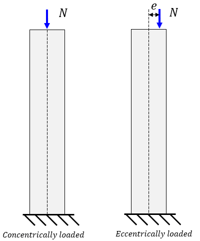
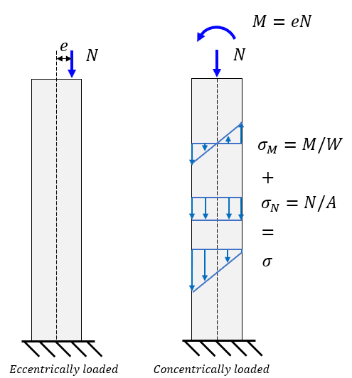
Combined loading occurs when an axial force acts eccentrically relative to the section's centroid or when a member is part of a frame transferring moments. The axial force causes uniform stress (\(\sigma_{axial} = N/A\)), while the bending moment causes linearly varying stress (\(\sigma_{bending} = M / W\)). The combined stress distribution determines the section's resistance. Importantly, a compressive axial force reduces the section's capacity to resist bending moment compared to pure bending.
In the figure below can is shown an eccentric load onto a column, which generates an additional moment. The peak internal stress is a combination of both the normal force N and the moment M.
Recap: The role of cross-section classification
As with individual checks, the method for verifying combined axial force and bending moment depends heavily on the cross-section class (determined according to §7.5). Refer to our Cross-Section Classification guide for details.
- Class 1 & 2 sections: Can utilize plastic stress distribution and resistance (\(M_{pl,Rd}, N_{pl,Rd}\)). Interaction formulas are often based on reduced plastic moment capacity (\(M_{N,Rd}\)).
- Class 3 sections: Limited to elastic stress distribution. Checks involve ensuring the maximum combined elastic stress does not exceed yield strength (\(f_y\)).
- Class 4 sections: Limited by local buckling before yield. Checks involve ensuring the maximum combined elastic stress, calculated using effective properties, does not exceed yield strength.
Design checks according to EN 1993-1-1 §8.2.9
Class 1 & 2 sections (plastic interaction)
For sections capable of plastic behaviour, the presence of axial force \(N_{Ed}\) reduces the plastic moment resistance \(M_{pl,Rd}\) to a value \(M_{N,Rd}\). The basic check is \( M_{Ed} \le M_{N,Rd} \).
When can interaction be neglected?
For doubly symmetrical I and H sections, you can ignore the effect of axial force on the major axis plastic moment resistance (\(M_{y,pl,Rd}\)) if BOTH conditions are met:
AND
Similarly, the effect on the minor axis plastic moment resistance (\(M_{z,pl,Rd}\)) can be ignored if:
Where \(N_{pl,Rd} = A f_y / \gamma_{M0}\), \(h_w\) is web depth, and \(t_w\) is web thickness.
Approximate interaction formulas
If interaction cannot be neglected, Eurocode provides practical approximate formulas for standard sections (assuming fastener holes are not critical):
For I/H sections (equal flanges):
- Major axis: \[ M_{N,y,Rd} = M_{pl,y,Rd} \frac{1-n}{1-0.5a} \le M_{pl,y,Rd} \]
- Minor axis and \( n \le a \) (No reduction if axial load primarily taken by web): \[ M_{N,z,Rd} = M_{pl,z,Rd} \]
- Minor axis and \( n > a \): \[ M_{N,z,Rd} = M_{pl,z,Rd} \left[ 1 - \left( \frac{n-a}{1-a} \right)^2 \right] \]
Where: \( n = N_{Ed} / N_{pl,Rd} \), \( a = (A - 2bt_f) / A \le 0.5 \) (proportion of area in web).
For RHS/welded box sections (equal flanges/webs):
- Major axis: \[ M_{N,y,Rd} = M_{pl,y,Rd} \frac{1-n}{1-0.5a_w} \le M_{pl,y,Rd} \]
- Minor axis: \[ M_{N,z,Rd} = M_{pl,z,Rd} \frac{1-n}{1-0.5a_f} \le M_{pl,z,Rd} \]
Where: \( n = N_{Ed} / N_{pl,Rd} \), \( a_w = \frac{A -2bt}{A} \le 0.5 \) (area proportion of webs), \( a_f = \frac{A-2ht}{A}\le 0.5 \) (area proportion of flanges).
Biaxial bending interaction
For Class 1 and 2 sections under axial load plus bending about both axes (\(M_{y,Ed}\) and \(M_{z,Ed}\)), the following interaction formula may be used:
Where \(M_{N,y,Rd}\) and \(M_{N,z,Rd}\) are the reduced moment resistances calculated considering \(N_{Ed}\). The exponents \(\alpha\) and \(\beta\) depend on the section type:
- Conservatively \(\alpha=\beta=1\),
- I/H \(\alpha=2, \beta=5n \ge 1\)
- CHS \(\alpha=\beta=2\)
- RHS \(\alpha=\beta=1.66 / (1-1.13n^2) \le 6\)
Where \(n=N_{Ed}/N_{pl,Rd}\)
Class 3 sections (elastic stress check)
For Class 3 sections, the design is based on ensuring the maximum longitudinal stress (\(\sigma_{x,Ed}\)) at the extreme fibres does not exceed the yield strength design value:
Where \(\sigma_{x,Ed}\) is calculated using the elastic superposition of stresses from axial force and bending moment(s), considering the gross cross-section properties (but potentially net area if tension occurs at fastener holes):
Calculate the stress at the critical point(s) (usually corners) and check against \(f_y / \gamma_{M0}\).
Class 4 sections (effective stress check)
For Class 4 sections, the check is similar to Class 3, but uses effective cross-section properties calculated according to EN 1993-1-5 to account for local buckling:
Where \(\sigma_{x,Ed}\) is the maximum longitudinal stress calculated using effective properties:
- \(A_{eff}\) is the effective area under compression.
- \(W_{eff,min}\) is the minimum effective elastic section modulus for bending about the relevant axis.
- \(e_{Ny}\) and \(e_{Nz}\) are the shifts in the centroid of the effective area relative to the gross area when under compression only, causing additional moments \(N_{Ed} e_N\).
Critical Limitation: The checks described in §8.2.9 verify the cross-section resistance only. Members subjected to combined compression and bending (beam-columns) are typically governed by buckling interaction checks according to EN 1993-1-1 §8.3. These checks consider flexural buckling, lateral-torsional buckling, and their interaction with the applied axial force and moments, accounting for member slenderness and imperfections. Section 8.3 checks are essential and must be performed in addition to the cross-section checks.
Interaction with high shear force
If high shear (\(V_{Ed} > 0.5 V_{pl,Rd}\)) is also present, the bending moment resistance terms (\(M_{pl,Rd}\), \(M_{N,Rd}\), or moments derived from \(W_{el}\) or \(W_{eff}\)) used in the axial-bending interaction checks should first be reduced according to the rules in §8.2.8 (see our Combined Shear and Bending guide).
Frequently asked questions (FAQ)
How does compression affect bending resistance?
Compression significantly reduces the plastic moment resistance (\(M_{pl,Rd}\)) for Class 1 & 2 sections as part of the cross-section's yield capacity is used by the axial load. For Class 3 & 4, it increases the maximum compressive stress, bringing it closer to the yield limit sooner.
Which interaction formula should I use for a Class 1 I-beam?
First check if interaction can be neglected. If not, use the approximate formulas for bending around a single axis or the biaxial formula Eq 6.41 if applicable. Remember to also check buckling (§8.3).
How do I check a Class 3 section?
Calculate the maximum combined longitudinal stress (\( \sigma_{x,Ed} = N_{Ed}/A \pm M_{y,Ed}/W_{el,y} \pm M_{z,Ed}/W_{el,z} \)) at the extreme fibres using elastic section properties and verify it's less than or equal to \(f_y / \gamma_{M0}\).
What are \(A_{eff}\) and \(W_{eff}\) for Class 4 sections?
They are the effective area and effective elastic section modulus, calculated according to EN 1993-1-5 by considering the reduced effective widths of slender plate elements under compression due to local buckling.
Is this cross-section check enough for a column design?
No. This check (§8.2.9) only verifies the cross-section capacity. For a compression member or beam-column, you must also perform member buckling checks according to §8.3, which consider slenderness and stability. Buckling resistance (\(N_{b,Rd}\), \(M_{b,Rd}\), and their interaction) often governs the design.
Conclusion
Verifying steel cross-sections under combined axial force and bending moment requires a method dependent on the section classification. Class 1 and 2 sections utilize plastic interaction formulas reducing the moment capacity (\(M_{N,Rd}\)). Class 3 sections are checked based on maximum elastic stress using gross properties, while Class 4 sections use a similar stress check but based on effective properties calculated per EN 1993-1-5, including effects of centroid shift. These cross-section checks are fundamental, but must always be supplemented by member buckling checks according to EN 1993-1-1 §8.3 for elements subjected to compression.