Steel Beam Bending Moment Check Explained (Eurocode 3 EN 1993-1-1 §8.2.5)
When beams bend under load, we need to ensure they are strong enough. This guide explains how to check the bending moment resistance (\(M_{c,Rd}\)) of steel sections using Eurocode 3. We'll focus on how the beam's cross-section classification is critical for performing this check correctly.
Quick Eurocode Bending Moment Check
Need results fast? Input your parameters into our Eurocode-based interactive calculator.
Go to Calculator →What is a bending moment?
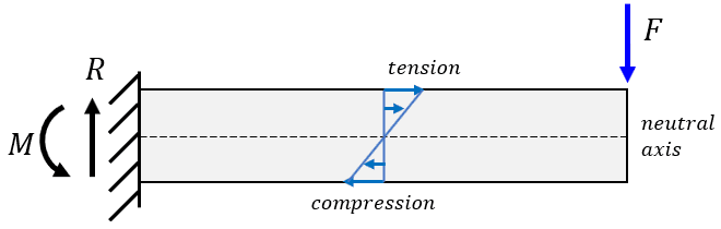
A bending moment (\(M\)) is an internal moment within a structural member caused by external transverse forces or moments. It creates internal tensile stresses on one side of the member's neutral axis and compressive stresses on the other, causing the member to curve or bend. The magnitude of the bending moment typically varies along the member's length and can be visualized using a bending moment diagram.
The role of cross-section classification
Before calculating bending resistance, you must classify the cross-section according to EN 1993-1-1 §7.5. As explained in our Cross-Section Classification guide, this determines how susceptible the section's compression elements are to local buckling. As shown in the figure below, cross section class 3 and 4 have a reduced limit for the bending stress. Design is based on:
- Class 1 & 2 sections: Plastic section modulus (\(W_{pl}\)).
- Class 3 sections: Elastic section modulus (\(W_{el,min}\)).
- Class 4 sections (slender): Effective section modulus (\(W_{eff,min}\)).
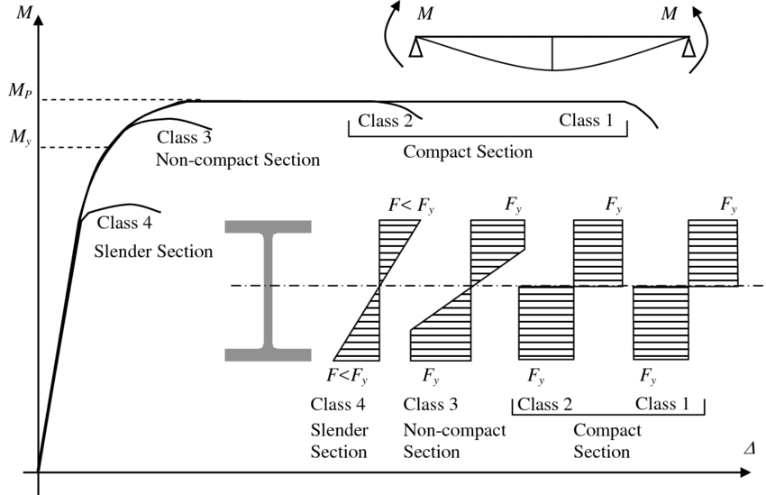
Source: ResearchGate (E.Y. Sayed-Ahmed), CC BY 4.0.
Design bending resistance calculation (\(M_{c,Rd}\)) (EN 1993-1-1 §6.2.5)
The design check
The design value of the bending moment (\(M_{Ed}\)) at any cross-section must satisfy:
Where \(M_{c,Rd}\) is the design bending moment resistance, and depends on the section class. Note that potential fastener holes must also be considered (see below).
- Resistance for class 1 & 2 sections (plastic resistance): These sections can develop their full plastic moment capacity before local buckling occurs.\[ M_{c,Rd} = M_{pl,Rd} = \frac{W_{pl} \times f_y}{\gamma_{M0}} \]
Where \(W_{pl}\) is the plastic section modulus about the relevant axis, \(f_y\) is the yield strength, and \(\gamma_{M0}\) is the partial safety factor (typically 1.00).
- Resistance for class 3 sections (elastic resistance): These sections can only reach the yield stress at the extreme fibres before local buckling prevents further plastification.\[ M_{c,Rd} = M_{el,Rd} = \frac{W_{el,min} \times f_y}{\gamma_{M0}} \]
Where \(W_{el,min}\) is the minimum elastic section modulus (corresponding to the extreme fibre where yield is first reached), \(f_y\) is the yield strength, and \(\gamma_{M0}\) is typically 1.00.
- Resistance for class 4 sections (effective section): Local buckling occurs before yield. The resistance must be based on effective section properties calculated according to EN 1993-1-5.\[ M_{c,Rd} = M_{eff,Rd} = \frac{W_{eff,min} \times f_y}{\gamma_{M0}} \]
Where \(W_{eff,min}\) is the minimum effective section modulus, calculated using the effective widths of the slender compression elements. Determining \(W_{eff,min}\) requires applying the methods outlined in EN 1993-1-5.
Determining section modulus (\(W_{pl}, W_{el}, W_{eff}\))
Section moduli quantify a cross-section's resistance to bending:
- \(W_{el}\) (Elastic): Calculated as \(I / y_{max}\), where \(I\) is the second moment of area and \(y_{max}\) is the distance from the neutral axis to the extreme fibre. Values for standard profiles are widely available in section property tables (available on Beam Profiles page). Use \(W_{el,min}\) for Class 3 checks if the section is unsymmetrical.
- \(W_{pl}\) (Plastic): Represents the moment capacity when the entire section has yielded. It depends on the location of the Plastic Neutral Axis (PNA), which divides the cross-section into two equal areas. Values are available for standard profiles. For symmetrical sections, \(W_{pl} / W_{el}\) (the shape factor) is typically > 1.0.
- \(W_{eff}\) (Effective): Calculated similarly to \(W_{el}\) but using the effective section properties (reduced widths/areas) obtained from EN 1993-1-5 calculations for Class 4 sections.
Consideration of fastener holes
Holes for bolts or other fasteners reduce the cross-section area and can affect bending resistance, particularly in the tension zone where fracture might occur. However, Eurocode allows holes to be ignored in certain cases:
- Holes in compression zone: Can generally be ignored if they are filled with fasteners (§8.2.5(6)). Slotted holes need to be accounted for.
- Holes in tension flange: May be ignored (§8.2.5(4)) provided the fracture resistance of the net area of the flange is greater than the yield resistance of the gross area of the flange. This check ensures yielding governs over fracture:\[ \frac{k \times A_{f,net} \times f_u}{\gamma_{M2}} \ge \frac{A_f \times f_y}{\gamma_{M0}} \]Where \(A_f\) is the gross area of the flange and \(A_{f,net}\) is the net area accounting for holes. The k factor accounts for the smoothness of the bolt hole and is either 0.9 or 1.0.
- Holes in web tension zone: Can be ignored (§8.2.5(5)) if the criterion above is satisfied for the entire tension zone (tension flange + tension part of the web).
If these conditions are not met, the effect of holes (reduced net area/section modulus) must be considered in the resistance calculation, which can be complex.
Important note on buckling & interaction effects
Critical Limitation: This guide covers only the cross-section bending resistance (\(M_{c,Rd}\)). For most beams, especially those unrestrained laterally, the design is governed by Lateral-Torsional Buckling (LTB) resistance (\(M_{b,Rd}\)). Always perform LTB checks where required.
Additionally, consider:
- Biaxial bending (§8.2.9): If moments (\(M_{y,Ed}\) and \(M_{z,Ed}\)) exist about both principal axes, interaction checks are needed.
- Shear interaction (§8.2.8): High shear force (generally \(V_{Ed} > 0.5 V_{pl,Rd}\)) can reduce the bending moment resistance. Check §8.2.8 if applicable.
- Combined bending and axial force (§8.2.9): Interaction checks are required if axial force (\(N_{Ed}\)) is also present.
- Lateral torsional buckling (LTB) (§8.3): For most beams, especially those unrestrained laterally, the design is governed by Lateral-Torsional Buckling resistance (\(M_{b,Rd}\)). LTB considers the member's length, end restraints, loading pattern, and cross-section shape.
Frequently Asked Questions (FAQ)
What is the difference between elastic (\(W_{el}\)) and plastic (\(W_{pl}\)) section modulus?
\(W_{el}\) relates the bending moment to the maximum stress at the extreme fibre assuming linear elastic behaviour (\(\sigma_{max} = M/W_{el}\)). \(W_{pl}\) relates the bending moment to the fully yielded state of the cross-section (\(M_{pl} = W_{pl} f_y\)) and is always larger than \(W_{el}\).
When do I use \(W_{pl}\), \(W_{el}\), or \(W_{eff}\)?
Use \(W_{pl}\) for Class 1 & 2 sections. Use \(W_{el,min}\) for Class 3 sections. Use \(W_{eff,min}\) for Class 4 sections.
Do I need to consider fastener holes for bending checks?
Sometimes. Holes in the compression zone filled with fasteners can usually be ignored. Holes in the tension zone can often be ignored if the condition in §8.2.5(4) (net section fracture capacity > gross section yield capacity) is met for the tension flange (or whole tension zone). If not met, their effect must be included.
What is Lateral-Torsional Buckling (LTB)?
LTB is a stability failure mode for beams bent about their major axis, where the compression flange buckles sideways and the section twists. It depends on the beam's unbraced length and cross-section properties. The LTB resistance (\(M_{b,Rd}\)) is calculated according to §8.3 and often governs the design of laterally unrestrained beams, resulting in a lower capacity than the cross-section resistance \(M_{c,Rd}\).