Axial Load Design (Tension & Compression) per Eurocode 3 (EN 1993-1-1)
Axial loads – forces acting along the longitudinal axis of a structural member – are fundamental in design. Members like columns, truss elements, and bracing are primarily subjected to either compression or tension. This guide explains how to check the cross-section resistance of steel members under axial load according to Eurocode 3 (EN 1993-1-1), covering key concepts like section classification, net area, effective area, and the relevant design checks.
What is axial load?
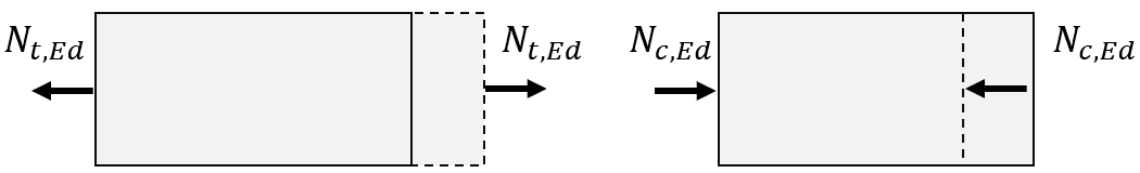
An axial load is a force applied parallel to the primary axis (the length) of a structural member.
- Tension: An axial load that tends to pull the member apart, elongating it.
- Compression: An axial load that tends to push the member together, shortening it (and potentially causing buckling).
Understanding how members resist these forces at the cross-section level is the first step in design, distinct from checking the overall member stability (buckling) for compression members.
Required concepts for axial design
Material properties
The steel material properties used in axial design checks are:
- Yield strength (\(f_y\)): The stress at which the material begins to deform plastically. Used for checks related to yielding or plastic capacity.
- Ultimate tensile strength (\(f_u\)): The maximum stress the material can withstand before fracturing. Used for checks related to fracture, particularly of the net section.
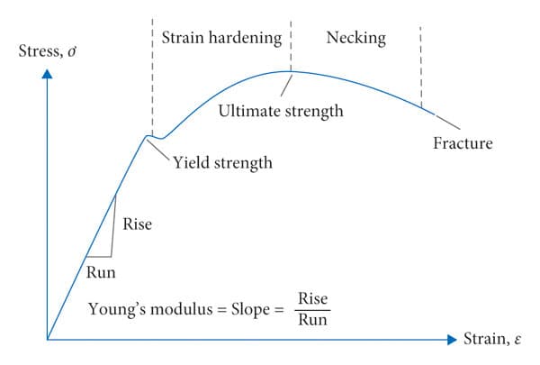
Source: ResearchGate (Nangulama et al.), CC BY 4.0.
Cross-sectional properties
Different area definitions are used depending on the check:
- Gross area (\(A\)): The total cross-sectional area of the member, ignoring any holes. Used for checking plastic resistance (yielding).
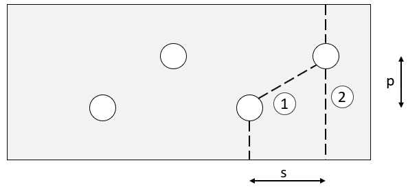
- Net area (\(A_{net}=A-A_{red}\)): The gross area minus deductions for fastener holes along potential failure paths. In the figure below are two failure paths defined. The smallest area must be used.
- Failure plane 1: \(A_{red}=t \left(n_1d_0-\sum{\frac {s^2} {4p}} \right)\)
- Failure plane 2: \(A_{red}=n_2 td_0\)
- \(A_1, A_2\): gross area along the failure plane
- \(d_0\): diameter of hole
- \(t\): plate thickness
- \(n_1, n_2\): number of holes in failure plane 1 or 2.
- \(s\): staggered pitch
- \(p\): spacing of centeres of hole
- Effective area (\(A_{eff}\)): Used for Class 4 sections in compression.
Cross-section classification (Classes 1-4)
Different checks are required depending on the cross-section class of the beam. See Cross section classification guide for more info on this topic. Classification classes are:
- Class 1 & 2: Design is based on plastic resistance using the gross area (\(A\)).
- Class 3: Design is based on elastic stress distribution, typically using the gross area (\(A\)) for axial checks.
- Class 4 (Slender): Design must be based on the effective area (\(A_{eff}\)), calculated using effective widths according to EN 1993-1-5.
Partial safety factors
Eurocode uses partial safety factors (\(\gamma_M\)) applied to material resistance:
- \(\gamma_{M0}\): Typically 1.00.
- \(\gamma_{M2}\): Typically 1.25.
Always check the relevant National Annex for applicable values.
Quick Eurocode Axial Strength Check
Need results fast? Input your parameters into our Eurocode-based interactive calculator.
Go to Calculator →Design for tension (EN 1993-1-1 §8.2.3)
Design check
The design value of the tension force (\(N_{Ed}\)) must satisfy:
Where \(N_{t,Rd}\) is the design tension resistance of the cross-section, taken as the smaller of the plastic resistance and the ultimate resistance.
Plastic resistance (gross section)
This check prevents yielding of the main member away from connections:
Where \(A\) is the gross cross-sectional area.
Ultimate resistance (net section at holes)
This check prevents fracture at the weakened cross-section where fastener holes are present:
Where \(A_{net}\) is the net area of the cross-section after deducting for fastener holes (refer to EN 1993-1-8 for calculation). The k factor accounts for the smoothness of the bolt hole and is either 0.9 or 1.0.
Determining \(N_{t,Rd}\)
The design tension resistance is the minimum value obtained from the two checks:
Considerations for special cases
Special rules apply in the following cases:
- Sections that are connected with outstands do have different rules. For angles connected by one leg and other asymmetrically connected beams see EN1993-1-8 for more details.
- In members with category C connections (bolted joints designed for slip resistance in SLS) the maximum tension should be reducted following arcticle 4
- For earth quake resistant designs, the design plastic resistance should be less than the ultimate resistance of the net sections at the holes of fasteners: \(N_{pl,Rd} \le N_{u,Rd}\)
Design for compression (EN 1993-1-1 §8.2.4)
Important Note: This section covers the cross-section resistance to compression only. Compression members must also be checked for buckling resistance (\(N_{b,Rd}\)) according to EN 1993-1-1 §8.3, which accounts for the member's length, end restraints, and cross-section shape. Buckling often governs the design of compression members.
Design check (cross-section)
The design value of the compression force (\(N_{Ed}\)) must satisfy:
Where \(N_{c,Rd}\) is the design compression resistance of the cross-section.
Resistance based on cross-section class
- For Class 1, 2, or 3 cross-sections: Resistance is based on yielding of the gross section.\[ N_{c,Rd} = \frac{A \times f_y}{\gamma_{M0}} \]
- For Class 4 cross-sections: Resistance is based on the effective area, accounting for local buckling.\[ N_{c,Rd} = \frac{A_{eff} \times f_y}{\gamma_{M0}} \]
The effective area \(A_{eff}\) is calculated based on the effective widths of the compressed plate elements, determined according to EN 1993-1-5.
Regular fastener holes filled with fasteners generally do not need to be deducted for compression checks (§8.2.4(3)). Slotted holes do need to be accounted for.
Class 4 section eccentricity (§8.2.2.5)
For Class 4 sections under compression, local buckling causes the effective load-carrying area (\(A_{eff}\)) to shift its centroid relative to the gross section's centroid. This shift, \(e_N\), induces an additional bending moment that must be considered in the design:
This moment must typically be combined with other moments acting on the member according to the interaction checks in §8.2.9 or §8.3.
Frequently Asked Questions (FAQ)
What is the main difference between tension and compression section checks?
Tension checks consider both yielding of the gross area (\(A\)) and fracture of the net area (\(A_{net}\)). Compression checks consider yielding based on either the gross area (\(A\) for Classes 1-3) or the effective area (\(A_{eff}\) for Class 4) due to local buckling, but also require a separate check for overall member buckling.
Why is \(\gamma_{M2}\) (1.25) used for net section fracture but \(\gamma_{M0}\) (1.00) for yielding?
Fracture is considered a more critical failure mode with less warning than yielding, hence a higher partial safety factor is applied (\(\gamma_{M2} > \gamma_{M0}\)) to achieve a higher level of safety against it.
What are cross-section Classes 1, 2, 3, and 4?
They classify how susceptible the parts of a cross-section are to local buckling when under compression. Class 1 is the most robust (can form plastic hinges), while Class 4 is the most slender (local buckling occurs before yielding), requiring the use of effective cross-section properties.
Do I always need to calculate \(A_{eff}\)?
Only for Class 4 cross-sections when they are subjected to compression (either from axial load or bending). Refer to EN 1993-1-1 Table 7.3 for classification limits and EN 1993-1-5 for calculating effective widths/area.