Clevis Joint & Pin Connection Design: A Practical Eurocode Guide (EN 1993-1-8)
Pin connections, including common clevis (or fork-end) joints, are fundamental components in structural and mechanical engineering, enabling rotation while transferring significant loads. Designing these connections robustly according to standards like Eurocode 3 (EN 1993-1-8) is essential for safety and functionality. This guide details the design checks, key parameters, practical advice, and links to our Clevis Joint Check calculator.
What are Pin Connections & Clevis Joints?
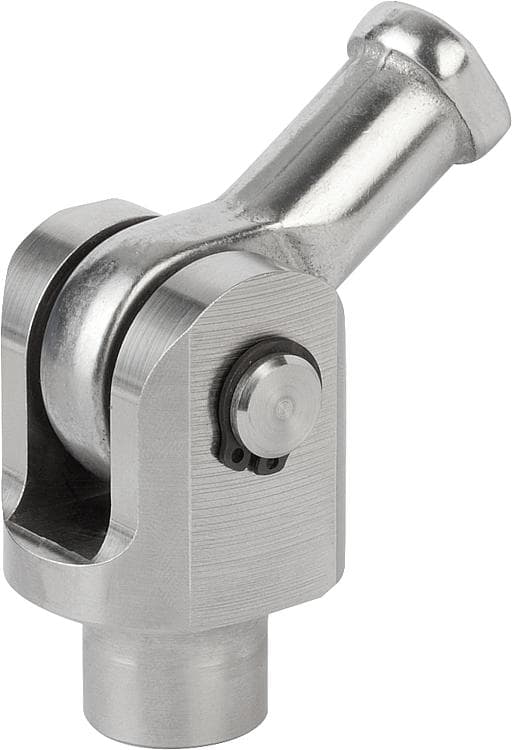
A pin connection uses a cylindrical pin inserted through holes in two or more members (lugs) to create a joint that primarily transfers shear loads while allowing relative rotation. A common configuration is the clevis joint (or fork-end joint), where a single central lug (tongue) fits between the two parallel plates of a U-shaped clevis (fork), all connected by the pin.
Key Terminology
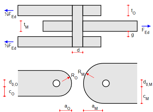
- Pin: The cylindrical member transferring the load via shear and bending. Diameter (\(d\)).
- Lug/Plate: The connected members with holes for the pin. Can be the outer 'fork' arms or the middle 'tongue'. Thickness (\(t\)).
- Clevis / Fork: The U-shaped component, typically comprising two outer lugs.
- Tongue: The single middle lug fitting inside the clevis fork.
- Hole Diameter (\(d_0\)): Diameter of the hole in the lugs.
- Gap: Space between middle and outer lugs (influences pin bending).
- Edge Distances (\(a, c\)): Distance from hole center to plate edges (parallel and perpendicular to load).
- Radius (\(R\)): Radius of the plates. The radius shall not be too small. The radius is not measured from the centre of the hole.
Importance of Correct Pin Connection Design
Failure in a pin connection can be catastrophic. Careful design ensures:
- Safe Load Transfer: The joint can handle the design loads (\(F_{Ed}\)) without exceeding material or component capacities.
- Prevention of Failure Modes: Addresses potential failures like pin shear, pin bending, lug bearing, lug shear tear-out, and lug net tension.
- Serviceability: Prevents excessive hole elongation under service loads (\(F_{ser}\)), especially important for functionality and fatigue.
- Code Compliance: Adheres to established safety standards like Eurocode 3.
Pin Connection Design Checks (Eurocode EN 1993-1-8 §5.4 and §5.5)
EN 1993-1-8, Chapter 5 provides design rules for pinned connections primarily loaded in shear. Several resistance checks must be performed for both the pin and the connected lugs (clevis fork arms and middle tongue). The given formulas are for the ultimate limit state (ULS) check. Refer to section 3.13 for requirements in the serviceability limit state (SLS) and for the required edge distances at the front and side.
Interactive Clevis Joint / Pin Check
Quickly verify your pin connection design against Eurocode checks using our calculator.
Go to Calculator →Pin Resistance Checks
The pin itself must be checked for:
- Shear Resistance (\(F_{v,Rd}\)): The pin must resist shearing across its cross-section(s). The resistance depends on the pin's ultimate tensile strength (\(f_{u,p}\)), cross-sectional area (\(A_p\)), and \(\gamma_{M2}\). Double shear applies in typical clevis joints.\[ F_{v,Rd} = \frac{0.6 \times f_{u,p} \times A_p}{\gamma_{M2}} \quad \text{(Single Shear)} \]\[ F_{v,Rd} = 2 \times \frac{0.6 \times f_{u,p} \times A_p}{\gamma_{M2}} \quad \text{(Double Shear)} \]
- Bending Resistance (\(M_{Rd}\)): If there's a significant gap between lugs then pin bending becomes critical. Resistance depends on the pin's yield strength (\(f_{y,p}\)), elastic section modulus (\(W_{el,p}\)), and \(\gamma_{M0}\). The maximum moment (\(M_{Ed}\)) depends on the load (\(F_{Ed}\)) and the geometry (gap, plate thicknesses). For the calculation of \(M_{Ed}\) assumptions have to be made. The formula below is assuming equal stress distribution over the whole thickness of the middle and outer lugs.\[ M_{Rd} = \frac{1.5\times W_{el,p} \times f_{y,p}}{\gamma_{M0}} \]\[ M_{Ed} = \frac{F_{Ed}}{8} \times (t_{M}+2t_{O}+4\times gap) \]
- Combined shear and bending: If both the shear and bending are high, then it could be that these forces combined are too much.\[ \left(\frac{M_{Ed}}{M_{Rd}}\right)^2 + \left(\frac{F_{v,Ed}}{F_{v,Rd}}\right)^2 \le 1.0\]
Connected Part (Lug/Tongue) Resistance Checks
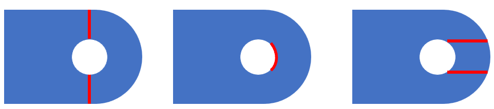
The plates connected by the pin must be checked for several failure modes at the pin hole location:
- Bearing Resistance (ULS, \(F_{b,Rd}\)): The plate material must resist crushing/yielding due to pressure from the pin. Depends on pin diameter (\(d\)), plate thickness (\(t\)), yield strength of the weakest material (\(f_{y}\)) and \(\gamma_{M2}\). (Ref EN 1993-1-8 §5.5).\[ F_{b,Rd} = \frac{1.5 \times f_y \times d \times t}{\gamma_{M2}} \]
- Lug Geometry Requirements: To ensure adequate strength and prevent premature failure, the lug/tongue geometry should meet the following minimum dimensions, based on the hole diameter (\(d_0\)) (EN 1993-1-8 Table 5.2). The calculation tool does also have different options for setting the geometry of the lugs.
- End distance: \(a \geq 1.1 d_0\)
- Edge distance: \(c \geq 0.75 d_0\)
- Plate thickness:\(t \geq 0.7 \sqrt{\frac{F_{Ed} \times \gamma_{M0}}{f_y}}\)
- Plate thickness: \(t \geq \frac{d_0}{2.5}\)
- Radius of lug: \(R \geq 1.3 d_0\)
Using the Structolution Clevis Joint Calculator
Our interactive tool performs the necessary checks according to EN 1993-1-8 based on your inputs.
- Loads: Enter design ultimate load (\(F_{Ed}\)) and serviceability load (\(F_{ser}\)).
- Pin Details: Input diameter (\(d\)), yield (\(f_{y,p}\)), ultimate strength (\(f_{u,p}\)), gap between lugs, and if the pin is replaceable (affects \(\gamma_{M6,ser}\) check).
- Lug Details (Middle/Outer): Input yield strength (\(f_y\)), hole diameter (\(d_0\)), plate thickness (\(t\)), front edge distance (\(a\)), and side edge distance (\(c\)).
- Factors: Set appropriate partial safety factors (\(\gamma_{M0}, \gamma_{M2}, \gamma_{M6,ser}\)) based on code/National Annex.
The tool calculates the resistance for each failure mode (pin shear, pin bending, pin bearing, lug bearing, lug shear, lug tension) in ULS and SLS and provides utilization ratios.
Practical Design Considerations
Beyond the strength checks:
- Tolerances: Pin and hole diameter tolerances are critical for load distribution and preventing excessive movement or binding. Standard clearance is usually 0.5mm to 1.0mm, but can vary depending on the application.
- Edge Distances & Spacing: Ensure sufficient edge distances (\(a, c\)) and spacing between holes to prevent premature failure modes as shown in the figure above.
- Material Selection: Choose appropriate steel grades for pin and lugs based on strength requirements and environmental conditions. Pin material is often stronger than lug material.
- Corrosion Protection: Pinned joints can be susceptible to crevice corrosion. Consider galvanizing, painting, or using corrosion-resistant materials.
- Installation & Maintenance: Consider ease of pin insertion/removal, especially if marked as 'replaceable'. Ensure proper lubrication if required for frequent movement.
Real-World Applications
Pin connections and clevis joints are found in numerous applications, including:
- Structural steel bracing and truss connections
- Lifting equipment (shackles, hooks, spreader beams)
- Mechanical linkages and control rods
- Hydraulic/pneumatic cylinder mounts
- Aerospace fittings and landing gear
- Bridge bearings
Frequently Asked Questions (FAQ)
What is the difference between a clevis and a simple lug?
A clevis typically refers to the U-shaped 'fork' with two parallel lugs, designed to accept a single central 'tongue' or lug. A lug can refer to any single plate with a pin hole forming part of the connection.
When is pin bending important?
Pin bending becomes more significant as the gap between the connected lugs increases, or if the load is applied eccentrically to the pin's shear planes. EN 1993-1-8 requires checking bending if the moment (\(M_{Ed}\)) is significant.
What does the serviceability bearing check prevent?
This check limits the bearing stress under service loads to prevent excessive elongation (ovalization) of the pin hole over time, which could affect the joint's function or lead to fatigue issues.
Are there minimum edge distance requirements?
Yes, EN 1993-1-8 Table 3.9 specifies minimum edge distances (\(a, c\)) and radius to ensure adequate resistance against bearing, shear, and tension failures.