Fillet Weld Design & Calculation: A Practical Eurocode Guide (EN 1993-1-8)
Fillet welds are fundamental in steel structures, providing efficient and strong connections. Designing them correctly according to Eurocode 3 (EN 1993-1-8) is crucial for safety and compliance. This practical guide breaks down fillet weld calculations, explains key parameters, covers design steps, and links to our easy-to-use calculation tool.
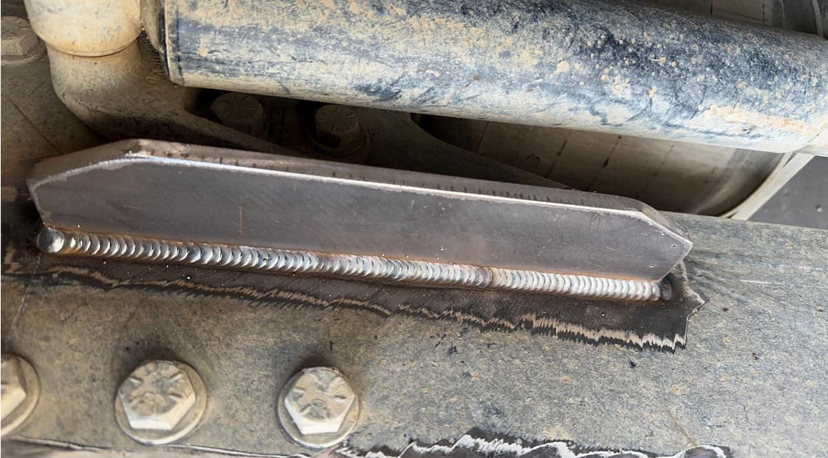
What is a Fillet Weld? Basics & Types
A fillet weld is used to join two pieces of material, typically meeting at an angle between 60° and 120° (most commonly 90°). This weld type uses a triangular cross-section to effectively join parts, often without needing edge preparation (e.g., beveling). The geometry and quality of the weld are critical to its load-bearing capacity.
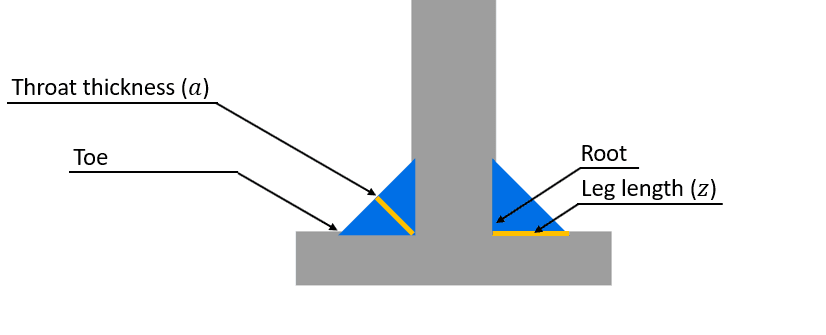
Key Terminology
- Leg Length (\(z\)): The distance from the root of the joint to the toe of the fillet weld along the base metal surface. Welds can have equal or unequal leg lengths.
- Throat Thickness (\(a\)): The minimum distance from the root of the weld to its face. This is the critical dimension for strength calculations.
- Weld Root: The point where the back of the weld intersects the base metal surfaces.
- Weld Toe: The junction between the face of the weld and the base metal.
Common Types & Profiles
Based on geometry, fillet welds are primarily:
- Equal Leg: Leg lengths (\(z\)) are the same on both sides.
- Unequal Leg: Used in specific situations where different leg lengths are required.
The face profile can be:
- Mitre (Flat): The ideal profile, often assumed in basic calculations.
- Convex: Curves outwards. Provides slightly more weld material but may increase stress concentration at the toes.
- Concave: Curves inwards. Generally results in a smaller throat thickness and can be prone to cracking if not done correctly.
Fillet Weld Strength Calculation (Eurocode EN 1993-1-8)
Eurocode 3 Part 1-8 provides methods to determine the design resistance of fillet welds. Depending on the loading conditions, you will either use a simplified method, or a more complex method to account for combined stresses.
Quick Eurocode Fillet Weld Check
Need results fast? Input your parameters into our Eurocode-based interactive calculator.
Go to Calculator →Simplified Method: Shear Resistance Only
The simplified method is suitable when the weld is subjected to shear forces parallel to its axis, and other stress components are negligible. This is typically applicable when the weld is loaded in pure shear. Other loads could also be checked with this method if you distribute the forces appropriate over the welded area.
Step 1: Determine Effective Throat Thickness (\(a\))
The throat thickness is critical. For an ideal fillet weld joining parts at 90° with equal leg length \(z\), the throat is:
Eurocode allows for calculating \(a\) for other angles and penetration welds, but this is the most common case. Ensure \(a\) is not less than 3mm (EN 1993-1-8 §4.5.2).
Step 2: Calculate Design Weld Shear Strength (\(f_{vw,d}\))
This represents the design shear stress capacity of the weld material itself. It's calculated based on the ultimate tensile strength (\(f_u\)) of the weaker base material being joined:
- \( f_u \): Nominal ultimate tensile strength of the weaker part. (e.g., 360 MPa for S235, 430 MPa for S275, 510 MPa for S355).
- \( \beta_w \): Correlation factor relating weld strength to parent metal strength (EN 1993-1-8 Table 4.1). It depends on the steel grade:
- \( \gamma_{M2} \): Partial safety factor for resistance of joints. Typically 1.25 according to Eurocode, but always verify the value specified in the relevant National Annex.
| Steel quality | \( \beta_w \) (-) |
|---|---|
| S235 | 0.8 |
| S275 | 0.85 |
| S355 | 0.9 |
| S420 | 1.0 |
| S460 | 1.0 |
Step 3: Calculate Design Resistance per Unit Length (\(F_{w,Rd}\) per mm)
The design shear resistance provided by the weld per millimeter of its length is found by multiplying the design shear strength by the throat thickness:
Step 4: Calculate Total Design Resistance (\(F_{w,Rd}\))
Multiply the resistance per unit length by the effective length of the weld (\(L_{eff}\)). The effective length is typically the overall length minus end returns or allowances for craters, if applicable. Often, the full length is reduced with two times the throat thickness.
The applied design shear force (\(F_{w,Ed}\)) must be less than or equal to this resistance: \( F_{w,Ed} \le F_{w,Rd} \).
Complex Method: Combined Stresses
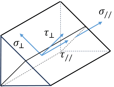
When the weld is subjected to forces other than pure shear parallel to its axis (e.g., tension/compression perpendicular to the weld, or shear perpendicular to the axis), a more detailed check is needed according to EN 1993-1-8 §4.5.3 The combined stresses in the weld throat must satisfy:
And the normal stress perpendicular to the throat must also satisfy:
- \( \sigma_{\perp} \): Normal stress perpendicular to the throat plane.
- \( \tau_{\perp} \): Shear stress in the throat plane, perpendicular to the weld axis.
- \( \tau_{\parallel} \): Shear stress in the throat plane, parallel to the weld axis (this is the primary stress used in the simplified method).
Our interactive calculator includes options to input these different force components and performs these checks automatically.
Simplify Your Calculations: Interactive Tool
Manually performing these checks can be time-consuming. Our Fillet Weld Check tool streamlines the process based on Eurocode 3:
- Input applied forces (\(F_{Ed}, M_{Ed}\)) along the x-, y- and z-axis.
- Select material grades (determines \(f_u\) and \(\beta_w\)).
- Define weld geometry (throat \(a\), length \(L\), plate thickness \(t\)).
- Specify geometry reduction factors (weld length reduction \(2a\), reduction for long welds \(\beta_{red}\)).
- Specify the partial safety factor \(\gamma_{M2}\).
- The tool calculates stresses, design resistance, and the final utilization ratio.
Practical Design & Welding Considerations
Beyond calculations, successful fillet welding involves practical aspects:
Material Selection and Preparation
Ensure compatibility between base metals and filler material. Thoroughly clean joint surfaces—remove rust, paint, oil, moisture, and scale. Ensure proper fit-up; excessive gaps increase weld volume and can compromise strength.
Welding Techniques
Use appropriate welding processes (SMAW, GMAW, FCAW, SAW). Maintain consistent parameters: travel speed, arc length/voltage, wire feed speed/amperage, and electrode angle. Control heat input to minimize distortion and residual stresses. Sequence welding carefully for complex joints.
Inspection and Quality Control
Visual inspection (VT) is the first line of defence, checking for surface defects like cracks, undercut, overlap, porosity, and incorrect weld size/profile. Non-Destructive Testing (NDT) methods like Magnetic Particle (MT), Dye Penetrant (PT), or Ultrasonic Testing (UT) may be required by specifications to detect subsurface flaws.
Common Mistakes to Avoid
- Using incorrect weld size (undersized = weak, oversized = wasteful).
- Inadequate cleaning leading to porosity or inclusions.
- Poor fusion or penetration at the root.
- Ignoring residual stresses and potential distortion.
- Not checking the requirements of the National Annex for \(\gamma_{M2}\) or \(\beta_w\).
Real-World Applications
Fillet welds are essential connections in:
- Building frames (beam-to-column, bracing connections)
- Bridge construction (stiffeners, girder connections)
- Machinery bases and frames
- Shipbuilding and offshore structures
- Automotive chassis and components
- Pressure vessels and tanks (often combined with groove welds)
Frequently Asked Questions (FAQ)
What's the minimum fillet weld size in Eurocode?
EN 1993-1-8 §4.5.2 recommends a minimum effective throat thickness \(a\) of 3 mm.
What's the minimum plate thickness size in Eurocode?
EN 1993-1-8 §4.1 recommends a minimum plate thickness \(t\) of 4 mm for welded joints.
How do you calculate fillet weld length \(l_{eff}\)?
The effective weld length \(l_{eff}\) used in resistance calculations is typically the actual length of the weld, sometimes reduced slightly to account for start/stop craters if they are not properly filled, which would make \(l_{eff}=L-2a\). Check code specifics (§4.5.1). Long connections can get an additional reduction.
What is the length reduction factor \(\beta_{red}\) for long welds?
The factor \(\beta_{red}\) (also often denoted as \(\beta_{Lw}\)) accounts for the non-uniform stress distribution in very long fillet welds, which can reduce their overall effectiveness. Eurocode 3 specifies reduction factors like \(\beta_{Lw.1}\) for lap joints longer than 150\(a\), or \(\beta_{Lw.2}\) for welds longer than 1.7m used for connecting transverse stiffeners. Applying this factor reduces the design resistance of the long weld.
Can fillet welds resist tension/compression?
Yes, but their primary strength is in shear along the throat. Tension or compression perpendicular to the throat (\(\sigma_{\perp}\)) must be checked using the stress component verification formulas.
What is the difference between \(z\) and \(a\)?
\(z\) is the leg length measured along the base metal. \(a\) is the effective throat thickness, the shortest distance from the root to the face, which is the critical dimension for calculating shear area (\( a \approx 0.707 z \) for equal leg 90° ideal welds).
What is Z-grade material (Eurocode) and when should it be used?
Z-grade materials, as defined in Eurocode EN 1993-1-10, refer to structural steel products with improved through-thickness properties. This means they have enhanced resistance to lamellar tearing, which is a type of cracking that can occur in welded joints when subjected to tensile stresses perpendicular to the rolled surface of the steel. These materials are specified with minimum through-thickness ductility requirements, categorized as Z15, Z25, and Z35, where the number indicates the minimum reduction of area in the through-thickness direction. Using Z-grade materials is particularly important in welded connections where significant through-thickness stresses are anticipated, such as in heavily restrained joints or thick plates.
When is there increased risk of lamellar tearing:
- Heavily Restrained Joints: Use Z-grade when welded joints are highly restrained, meaning they cannot freely deform under stress. This often occurs in thick plates or complex connections.
- Thick Plates: In thick plates, especially when welded, there's a higher risk of lamellar tearing due to the increased restraint and through-thickness stresses.
- T-Joints and Cruciform Joints: These joint types often induce significant through-thickness stresses, making Z-grade steels a good choice.
- Welded Connections Subject to High Tensile Stress: When welded connections are subject to high tensile stresses perpendicular to the plate surface, Z-grade materials provide added safety.
- Fatigue-Critical Welded Connections: Lamellar tearing can initiate cracks that propagate under fatigue loading. Z-grade steel improves the fatigue resistance of welded joints.
Using Z-grade materials is a design decision that should be based on a thorough stress analysis of the welded connection. Always consult EN 1993-1-10 and relevant National Annexes for specific requirements.