Steel Cross-Section Classification Explained (Eurocode 3 EN 1993-1-1 §7.5)
Correctly classifying a steel cross-section is one of the first steps for verifying a beam. This classification determines how susceptible the section is to local buckling under compression (from axial load or bending) and dictates the appropriate analysis methods and resistance calculations. This guide explains the four section classes defined in EN 1993-1-1 §7.5 and how to determine them.
What is local buckling?
Local buckling is a phenomenon where thin plate elements making up a cross-section (like flanges or webs) buckle under compressive stress before the overall member fails or the material reaches its full yield strength across the entire section. This buckling reduces the element's ability to carry further stress. Classification aims to quantify this effect.
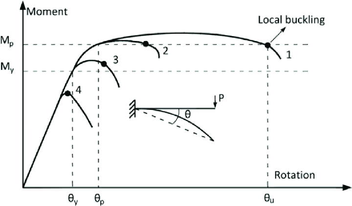
Source: ResearchGate (Wang et al.), CC BY 4.0.
Why classify cross-sections?
The primary purpose of classification is to identify the extent to which the resistance (e.g., moment capacity, compression capacity) and rotation capacity (ability to form plastic hinges) of a cross-section are limited by local buckling effects. This dictates:
- Which type of structural analysis can be used (e.g., elastic vs. elasto-plastic vs. plastic global analysis).
- Which formulas to use for calculating cross-section resistance (based on gross section properties vs. effective section properties).
- Practically speaking, it affects how you need to check the ultimate limit case (ULS) of the section. It affects the checks for, among others, tension (§8.2.3), compression (§8.2.4), bending (§8.2.5), shear (§8.2.6), combined loading (§8.2.9, §8.2.10).
The four classes defined (EN 1993-1-1 §7.5.2)
Eurocode 3 defines four classes based on the behaviour of the section's compression elements:
- Class 1 (Plastic): Sections where the compression elements are very robust ('stocky'). They can reach their full plastic moment resistance AND form a plastic hinge with sufficient rotation capacity for plastic analysis without any reduction due to local buckling.
- Class 2 (Compact): Sections where compression elements are slightly more slender. They can still develop their full plastic moment resistance, but local buckling limits their rotation capacity. Plastic design is often possible, but hinge rotation checks might be needed.
- Class 3 (Semi-Compact): Sections where compression elements are more slender still. The extreme compression fibre can reach the yield strength (\(f_y\)) under an assumed elastic stress distribution, but local buckling prevents the development of the full plastic moment resistance across the section. Design must be based on elastic principles.
- Class 4 (Slender): Sections containing slender compression elements. Local buckling occurs before the yield stress is reached in these elements. Design must account for this reduced capacity by using effective cross-section properties (effective widths \(b_{eff}\) / effective area \(A_{eff}\)) calculated according to EN 1993-1-5.
Source: ResearchGate (Tuyishimire et al.), CC BY 4.0.
How to classify a cross-section
Classification involves assessing each part of the cross-section that is (partially) under compression for the load case being considered. The various parts under compression can, in general, be in a different class.
1. Identify compression parts
Determine which elements (flanges, web) are fully or partially in compression. This depends on the applied loads (axial force, bending moment). Differentiate between:
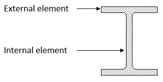
- Internal compression elements: Supported along both longitudinal edges (e.g., the web of an I-section in bending, flanges of a box section).
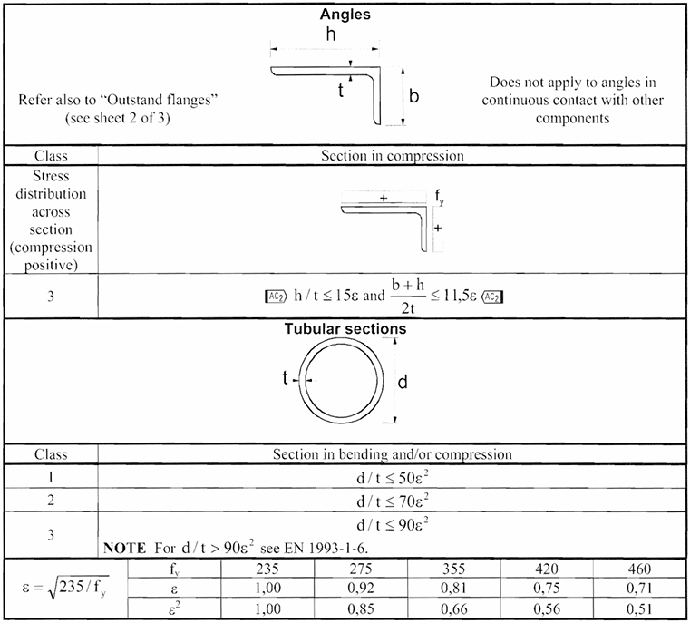
- Outstand compression elements: Supported along only one longitudinal edge (e.g., the compression flange of an I-section, legs of an angle section).
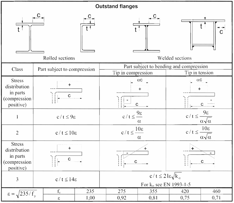
2. Calculate width-to-thickness ratios (\(c/t\))
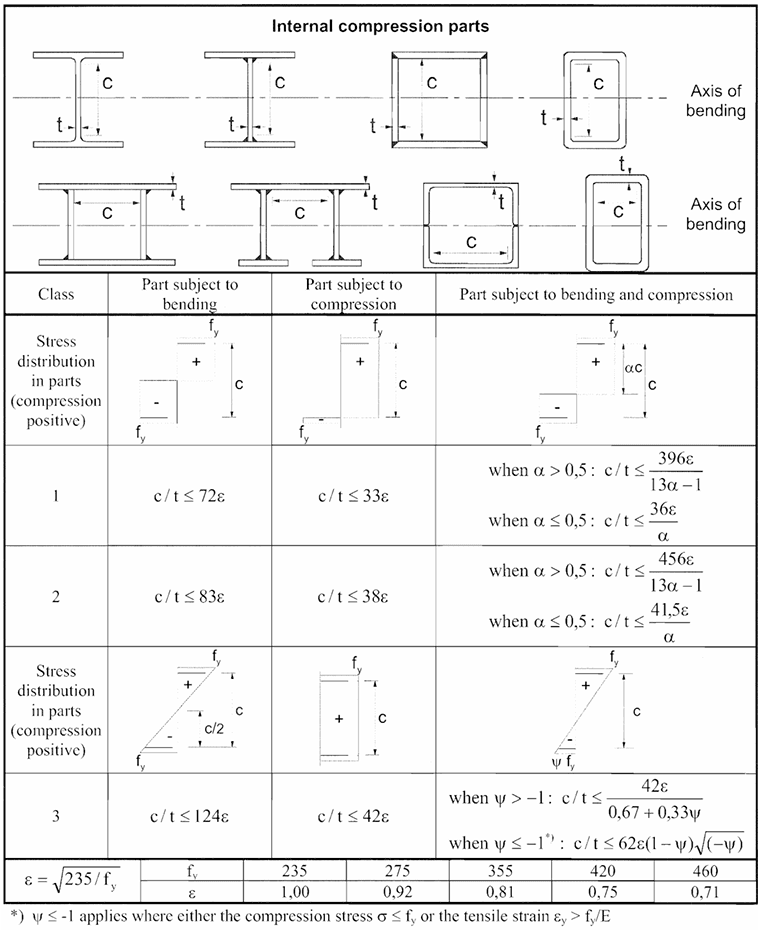
For each compression part, calculate the relevant width (\(c\)) and thickness (\(t\)). The definition of \(c\) depends on the element type (internal or outstand) and is specified in EN 1993-1-1 Table 7.3. For example, for an outstand flange, \(c\) is usually the distance from the root/support to the free tip; for an internal web, \(c\) is often the clear depth between flanges.
3. Determine epsilon (\(\epsilon\))
This factor accounts for the material's yield strength (\(f_y\) in MPa). It normalizes the limiting ratios for different steel grades.
For example, for S235 steel (\(f_y = 235 \text{ MPa}\)), \(\epsilon = 1.00\). For S355 steel (\(f_y = 355 \text{ MPa}\)), \(\epsilon \approx 0.81\).
4. Use EN 1993-1-1 Table 7.3
This crucial table provides the limiting width-to-thickness ratios (\(c/t\)) for Class 1, Class 2, and Class 3 for various types of compression parts (internal/outstand) and stress distributions (e.g., uniform compression, bending). The limits are expressed in terms of \(\epsilon\).
5. Determine Class of each compression part
Compare the calculated \(c/t\) ratio for each compression part to the limits in Table 7.3 for the appropriate stress distribution.
- If \(c/t \le \text{Class 1 limit}\), the part is Class 1.
- If \(\text{Class 1 limit} < c/t \le \text{Class 2 limit}\), the part is Class 2.
- If \(\text{Class 2 limit} < c/t \le \text{Class 3 limit}\), the part is Class 3.
- If \(c/t > \text{Class 3 limit}\), the part is Class 4.
6. Determine overall section Class
According to §7.5.2(5), the overall classification of the cross-section is determined by the highest (least favourable) class of any of its compression parts. For example, if a beam has Class 1 flanges but a Class 3 web under the given loading, the entire cross-section is classified as Class 3 for design checks related to that loading.
(Note: §7.5.2(11) provides an exception allowing Class 3 webs with Class 1/2 flanges to sometimes be treated as Class 2 sections with a reduced effective web area, see §8.2.2.4).
Frequently Asked Questions (FAQ)
What's the main difference between Class 3 and Class 4?
In a Class 3 section, the steel can reach its yield strength (\(f_y\)) just before local buckling occurs. In a Class 4 section, local buckling occurs at a stress below the yield strength, meaning the full section cannot yield before buckling initiates.
Does classification change depending on the load?
Yes. Classification depends on which parts are in compression and the stress distribution. A section might be Class 1 under pure bending but Class 3 or 4 under pure compression if the web becomes fully compressed.
What is EN 1993-1-5 used for?
EN 1993-1-5 (Plated structural elements) provides detailed rules for designing plate elements subject to buckling, including the methods for calculating effective widths and effective areas needed for Class 4 section design.
What are the impications of cross-section class on design checks?
The cross-section class directly impacts how you calculate its resistance. By understanding the definitions of Classes 1-4, identifying compression elements, calculating width-to-thickness ratios, and consulting Table 7.3, engineers can correctly account for the effects of local buckling and ensure safe, efficient designs. Remember that for Class 4 sections, further reference to EN 1993-1-5 is required to calculate effective properties.