Beam Analysis Explained: Guide to understand supports, loads, and interpret diagrams
Beams are essential structural elements designed to resist loads primarily through bending. Understanding how beams behave under load – calculating internal forces and deflections – is fundamental to safe and efficient structural design. This guide covers the core concepts of beam analysis, including equilibrium, supports, loads, shear & moment diagrams, deflection, and links to our comprehensive Beam Analysis tool.
What is Beam Analysis?
Beam analysis is the process of determining the internal forces (axial force, shear force, bending moment) and the resulting deflections that occur within a beam subjected to external loads and support conditions. It allows engineers to:
- Understand the load types and distribution.
- Calculate the reaction forces at the supports.
- Verify if the beam can safely withstand the applied loads without breaking or yielding (Strength Check).
- Ensure the beam does not deflect excessively under load (typically vertical deflection in the Z-direction), maintaining functionality and aesthetic requirements (Serviceability Check).
- Optimize the beam's size and shape for efficiency (using appropriate profiles like IPE, HEA etc.).
Fundamental concepts
Equilibrium
The foundation of beam analysis (and statics in general) is equilibrium. For a beam not accelerating, the sum of all forces in the horizontal (X) and vertical (Z) directions, and the sum of moments about the axis perpendicular to the XZ plane (Y-axis), must equal zero:
These equations allow us to calculate unknown support reactions. Do note that a xz-plane is used.
Beam properties (E and I)
A beam's resistance to bending and deflection depends on its material and cross-sectional shape:
- Young's modulus (\(E\)): A material property representing its stiffness (resistance to elastic deformation). Our calculator uses \(E = 210000\) MPa for steel by default.
- Moment of inertia (\(I\)): A geometric property of the beam's cross-section representing its resistance to bending. A larger \(I\) means less bending for the same moment. Selecting a beam profile (like IPE 80) in our tool automatically uses its known \(I\) value. Find properties on our Beam Profiles page.
Understanding support types
Supports provide reaction forces and moments to keep the beam in equilibrium. The type of support dictates which movements are restrained (X=horizontal, Z=vertical, Ry=rotation about Y). Our tool supports:
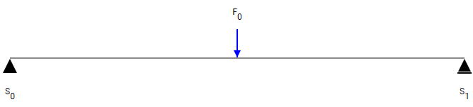
- Hinged / Pinned Support: Prevents translation (movement) in X and Z directions but allows rotation about Y. Provides vertical (\(R_z\)) and horizontal (\(R_x\)) reaction forces.
- Roller Support: Prevents translation only perpendicular to the rolling surface (typically Z direction) but allows rotation (about Y) and movement parallel to the surface (X direction). Provides only a vertical reaction force (\(R_z\)).
- Fixed Support: Prevents all translation (X and Z) and rotation (about Y). Provides vertical (\(R_z\)), horizontal (\(R_x\)), and moment (\(M_{Ry}\)) reactions.
- Spring Support - Vertical (\(k_z\)): Resists vertical (Z) translation. Reaction force is proportional to vertical displacement.
- Spring Support - Horizontal (\(k_x\)): Resists horizontal (X) translation. Reaction force is proportional to horizontal displacement.
- Spring Support - Rotational (\(k_{ry}\)): Resists rotation about the Y-axis. Reaction moment is proportional to rotation.
The type and position of supports determine if a beam is statically determinate (reactions found by equilibrium alone) or indeterminate (requires considering deflection).
Understanding load types
Loads are the external forces or moments applied to the beam. Our tool supports:
- Point Load: A concentrated force applied at a single point. Can have vertical (\(F_z\)) and/or horizontal (\(F_x\)) components.
- Moment Load: A concentrated twisting force applied at a single point \(T_y\) about the Y-axis.
- Distributed Load: A force spread over a length of the beam, measured in force per unit length (e.g., kN/m). Can be:
- Uniform (UDL): Constant intensity (\(q\)).
- Linearly Varying (Triangular/Trapezoidal): Intensity changes linearly from \(q_{start}\) to \(q_{end}\).
- Can have components parallel and perpendicular to the beam axis.
Internal forces, shear & moment diagrams
Internal forces (axial N, shear Vz, moment My)
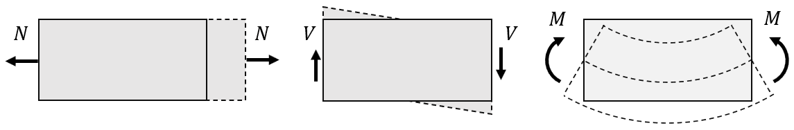
When external loads are applied, internal forces develop within the beam to maintain equilibrium. At any cross-section, we consider:
- Axial force (\(N\)): Tension or compression acting along the beam's axis (X-direction). Included in our tool via \(F_x\) loads.
- Shear force (\(V\) or \(V_z\)): Force acting perpendicular to the beam's axis in the Z-direction, tending to cause sliding between sections.
- Bending moment (\(M\) or \(M_y\)): Moment acting about the axis perpendicular to the XZ plane (the Y-axis), causing the beam to bend.
What are shear & moment diagrams?
These are crucial diagrams used in beam analysis:
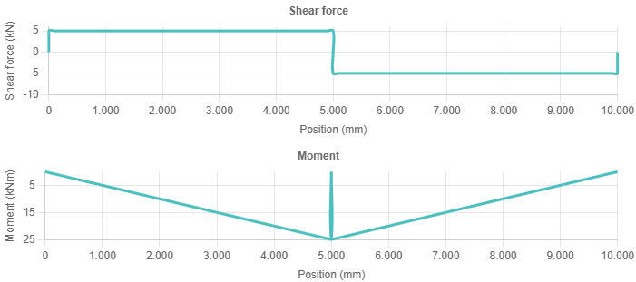
- Shear force diagram: Plots the internal shear force (\(V_z\)) along the length of the beam.
- Bending moment diagram: Plots the internal bending moment (\(M_y\)) along the length of the beam.
Why are shear force & moment diagrams important?
Shear and moment diagrams visually show how internal forces vary, allowing quick identification of:
- Locations and magnitudes of maximum shear force (\(V_{z,max}\)) and maximum bending moment (\(M_{y,max}\)). These values are critical for checking the beam's strength against shear failure and bending failure (yielding or fracture).
- Points of zero shear (often corresponding to maximum moment).
- Points of contraflexure (where the bending moment changes sign).
Interpreting diagrams & relationships
Key relationships help in construction and interpretation (where \(q(x)\) is the intensity of the load in the Z-direction):
- The slope of the shear diagram at any point equals the negative intensity of the distributed load: \( dV_z/dx = -q(x) \). (Constant shear under no load, linear shear under uniform distributed load, etc.)
- The slope of the moment diagram at any point equals the value of the shear force: \( dM_y/dx = V_z(x) \). (Linear moment under constant shear, parabolic moment under linear shear, etc.)
- The change in moment between two points equals the area under the shear diagram between those points.
- Point loads (\(F_z\)) cause sudden jumps in the shear force diagram. Point moments (\(M_y\)) cause sudden jumps in the moment diagram.
Calculating beam deflection
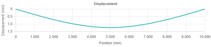
Deflection (\(\delta_z\) or \(w(x)\)) is the vertical displacement (in the Z-direction) of the beam from its original position due to applied loads. It's primarily governed by the beam's bending stiffness (\(EI\)) and the total internal moment (\(M_y\)).
Calculating deflection is crucial for serviceability checks – ensuring the beam doesn't sag too much, which can affect finishes, non-structural elements, or user comfort. Excessive deflection can also indicate potential instability.
Methods for calculating deflection include double integration of the moment-curvature relationship (\( EIw''(x) = M_y(x) \)), moment-area theorems, conjugate beam method, or numerical methods like the Finite Element Method (FEM), which is often employed by analysis software like our tool.
Using the structolution beam analysis tool
Our interactive Beam Analysis tool performs these calculations efficiently using numerical methods.
- Inputs: Define the beam's total length, select a standard profile (like IPE 80), specify supports (type and position), and add loads (type, position, magnitude like `Fx`, `Fz`, `My`, `q`).
- Process: Click 'Analyze'. The tool sends the model data for analysis (using FEM).
- Outputs: The results include diagrams for shear force (\(V_z\)), bending moment (\(M_y\)), and displacement (\(w(x)\)), maximum shear and moment, and a table of support reactions.
Practical considerations & assumptions
- Euler-Bernoulli Theory: Basic beam analysis usually assumes linear elastic material behavior, small deflections, and that plane sections remain plane after bending.
- Support Idealization: Real-world supports may not be perfectly pinned, fixed, or roller. Judgment is needed to select the appropriate model.
- Load Idealization: Loads are often simplified as point or uniformly distributed loads.
- Local Effects: Basic beam theory doesn't typically cover local web buckling, flange yielding, or stress concentrations near loads/supports. These may require separate checks.
- Units: Ensure consistent units are used throughout calculations (e.g., N, mm, MPa).
Frequently Asked Questions (FAQ)
What causes bending moment in a beam?
Bending moment is caused by external forces (loads and reactions) acting perpendicular to the beam's axis at a distance, creating a tendency for the beam to bend or rotate.
Where is the maximum bending moment usually found?
Maximum bending moment often occurs where the shear force is zero (or changes sign). For a simply supported beam with a uniform load, it's at the mid-span.
What is the difference between shear force and bending moment?
Shear force (\(V_z\)) is the internal force acting perpendicular to the beam's axis (in the Z-direction), resisting sliding. Bending moment (\(M_y\)) is the internal moment (about the Y-axis) resisting bending or rotation.
Why is deflection important in beam design?
Excessive deflection (typically vertical, \(\delta_z\)) can impair the function of the structure, damage non-structural elements (like partitions or glazing), cause undesirable vibrations, or be aesthetically unacceptable. Design codes typically specify deflection limits for serviceability.
What beam properties resist bending?
Resistance to bending depends on the material stiffness (Young's Modulus, \(E\)) and the cross-section's shape and size (Moment of Inertia, \(I\)). The product \(EI\) is the flexural rigidity.